.png)

In manufacturing estimating, even small input errors can significantly impact cost calculations and final quotes.
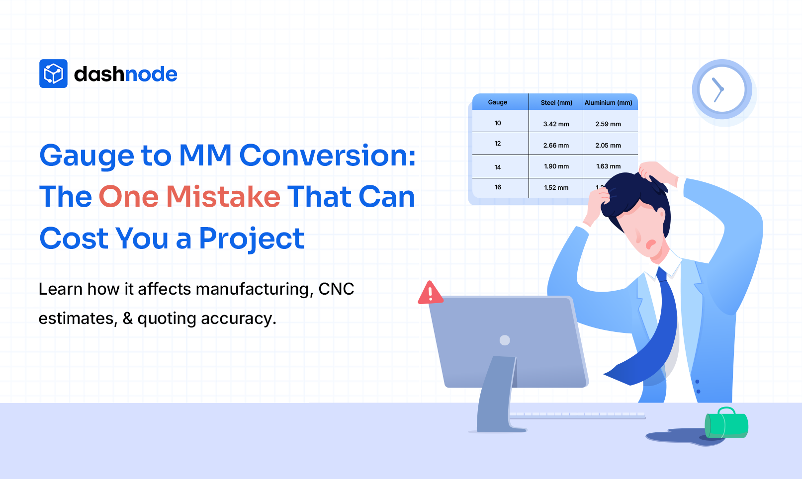
A fabrication shop receives an RFQ for a sheet metal enclosure. The drawing specifies 16-gauge steel for the outer panels. The estimator quickly converts the thickness into millimetres to calculate material weight, cutting time, and bending requirements.
However, the conversion used the wrong reference chart.
Instead of 1.52 mm steel, the estimate used 1.63 mm, which corresponds to a different standard. The difference appears small, but it affects material weight, cutting parameters, and bending force calculations.
By the time production begins, the shop realizes the thickness assumption was incorrect. Material costs and machine settings must be adjusted, delaying the project and impacting the margin.
Situations like this occur more often than many manufacturing teams expect. Gauge to mm conversion is a routine step when working with sheet metal specifications, fabrication drawings, or RFQs. Since gauge system is not universal, misunderstanding it can lead to incorrect engineering calculations.
Similar estimation challenges also arise in CNC machining and block machining workflows, where minute variations in inputs can significantly affect machining time and cost calculations. As RFQ volumes increase, maintaining consistency across these calculations becomes more challenging without a structured estimating system.
Even small errors in metal thickness interpretation can affect:

Understanding how gauge systems work and how to correctly convert them into millimetres is essential for engineers and estimators preparing manufacturing quotes.
In sheet metal fabrication, gauge is a numerical system used to represent the thickness of metal sheets.
Unlike metric measurements such as millimetres, gauge numbers work in reverse:
For example:
The gauge system originated in wire manufacturing, where the number indicated the number of drawing operations required to produce a specific wire thickness. Over time, the same numbering system was adopted for sheet metal.
However, one of the biggest challenges with the gauge system is that it is not standardised across all materials.
The thickness represented by a gauge number depends on the material type. Common systems include:
For instance:

The same gauge number can therefore represent different thickness values depending on the material.
Because of this variation, engineers rely on sheet metal gauge charts and metal thickness tables when converting gauge measurements into millimetres.
Although gauge charts are widely available, the conversion process can still cause confusion in engineering and estimating workflows.
Several factors contribute to these errors.
A 16 gauge steel sheet is not the same thickness as 16 gauge aluminum. Each material follows its own thickness standard.
If the wrong chart is referenced, the resulting mm conversion will be inaccurate.
Some fabrication teams still rely on older printed charts or legacy spreadsheets for gauge conversions. These references may follow outdated standards or fail to distinguish clearly between materials.
Different engineering resources may list slightly different values due to rounding or standard variations. When estimators rely on multiple sources, these inconsistencies can create confusion.
Because gauge numbers work in reverse order, they can easily be misunderstood. Engineers unfamiliar with the system may assume a higher gauge number means thicker material.

To avoid these problems, engineers and estimators should always verify thickness values using accurate sheet metal gauge charts.
Engineers frequently use sheet metal gauge charts to translate gauge numbers into millimetres during fabrication planning and quoting.
Below is a simplified metal thickness table for common steel and aluminum gauges.
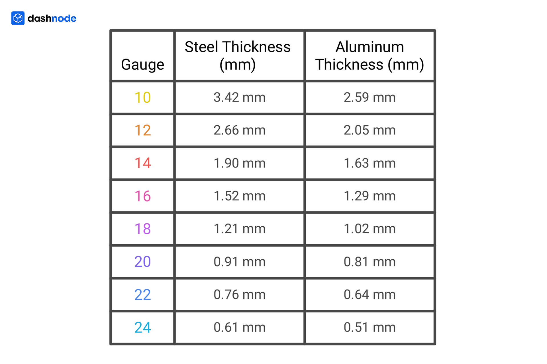
During the quoting process, engineers use these metal thickness tables to determine:
Even though gauge numbers appear simple, accurate mm conversion requires referencing the correct chart for the specific material.
In manufacturing environments, even small variations in material thickness can influence production calculations.
Estimators often use material thickness to calculate cutting speeds and cycle times for processes such as laser, plasma, or waterjet cutting. Incorrect thickness values can lead to inaccurate time estimates.
Sheet metal bending calculations depend heavily on thickness. A small change in thickness can increase the press brake tonnage required, affecting both tooling selection and cycle time.
If sheet metal parts include secondary machining operations such as milling or drilling, thickness values influence cutting parameters and estimated machining time.
Material thickness directly affects weight calculations. Incorrect thickness assumptions can distort:
Precision assemblies depend on accurate material specifications. Incorrect thickness interpretation can cause tolerance issues during fabrication or assembly.
Because many manufacturing calculations rely on thickness values, accurate gauge-to-mm conversion is critical during both engineering planning and quoting.

Even when reference charts are available, several common mistakes still occur in manufacturing environments.
A common error is assuming that steel gauge values apply to aluminum or stainless steel. Because each material uses different thickness standards, this assumption can lead to incorrect calculations.
Some companies rely on internally created spreadsheets that may not reflect updated engineering standards.
Gauge values do not follow a linear mathematical formula, so attempting manual conversions without reference charts can easily produce incorrect results.
Manufacturing drawings often contain both inch-based and metric dimensions. Converting gauge values into millimetres while working with imperial units can introduce calculation errors.

Small mistakes like these can eventually affect production planning and quoting accuracy.
Manufacturing teams typically use several best practices to reduce the risk of conversion mistakes.
Always confirm gauge values using reliable engineering references. Accurate sheet metal gauge charts should clearly differentiate between materials.
Engineering standards evolve over time. Teams should ensure that internal documentation reflects current thickness tables.
Modern CAD systems often include built-in material libraries that specify thickness values. These tools reduce the need for manual conversion.
During the quoting process, estimators often verify key inputs such as:
This additional verification step helps ensure consistent manufacturing calculations before a quote is generated.
Preparing a manufacturing quote involves numerous engineering calculations.
Estimators frequently evaluate variables such as:

Each calculation depends on reliable engineering data.
If a thickness value is misinterpreted early in the quoting process, the resulting errors can propagate through multiple calculations.
In many companies, these calculations are still performed using spreadsheets and manual reference charts. While spreadsheets are flexible, they can also introduce inconsistencies such as:

As manufacturing operations grow more complex, maintaining consistent calculation workflows becomes increasingly important for estimating teams.
To reduce inconsistencies in estimating workflows, many manufacturing companies are adopting structured quoting systems.
While the above example focuses on sheet metal inputs, similar challenges exist in CNC machining, where small inconsistencies in engineering data can impact machining time and cost estimates.
Dashnode is designed to address these challenges by automating production costing and standardizing how engineering inputs are interpreted during quoting.
In CNC machining, inaccuracies in inputs, such as dimensions, tolerances, or material properties, can lead to incorrect machining time estimates and inconsistent quotes.
This becomes even more critical in operations such as block machining, where factors like material removal volume, toolpath complexity, and machining strategy directly influence cycle time and cost. Estimating these parameters manually can lead to variations in quotes, especially when similar parts are interpreted differently across projects or teams.
For companies handling high volumes of RFQs, structured estimating workflows improve speed, consistency, and overall quoting accuracy. By reducing repetitive manual calculations, teams can focus more on evaluating production feasibility and less on managing scattered data.
With Dashnode, teams can:

Dashnode helps minimize these risks by standardizing how inputs are interpreted and automating CNC quoting workflows.
Improving quoting accuracy is not about eliminating every small mistake; it is about building workflows that make those mistakes less likely.
In CNC machining, consistent interpretation of input directly affects cost estimation and production planning.
If your team still relies on spreadsheets and manual calculations, it may be time to move toward a more structured approach.
Book a free demo of Dashnode to streamline estimating workflows, reduce calculation errors, and generate faster, more consistent CNC quotes.
Gauge is a numerical system used to indicate sheet metal thickness. Lower gauge numbers represent thicker material, while higher numbers represent thinner sheets.
Gauge values are converted using a sheet metal gauge chart, which lists the corresponding thickness in millimetres for each material type.
No. Steel and aluminum gauges follow different thickness standards, meaning the same gauge number can represent different thicknesses.
Small variations in inputs such as material thickness, tolerances, or dimensions can impact machining time, material cost, and overall production estimates, leading to inaccurate quotes.
By standardizing how inputs are interpreted and reducing manual calculations, manufacturers can improve consistency in estimates. Structured quoting systems help ensure that engineering data is applied accurately across projects.